USB Interface (XUP Series)
The modules of the XUP series (XUP01L, XUP01R) are connected to the controlling PC via a modern USB connection. Internally, the industry-standard FTDI (FT232) chip is used.
Pin Assignment
The connection is made via a USB Type B socket (classic "printer cable format" for robust retention).

| Pin | Signal | Description |
|---|---|---|
| 1 | VCC | 5V Supply (Load approx. 1mA) |
| 2 | USBDM | USB Data Minus (D-) |
| 3 | USBDP | USB Data Plus (D+) |
| 4 | GND | Ground |
IMPORTANT: External Power Supply
The module draws only minimal current via Pin 1 (VCC) for detection (~1mA). It is not powered via the USB bus! Even during USB operation, the external Logic Supply (8 .. 30 VDC) must be connected to the terminals Ub+ / Ub-.
Basic Circuit Diagram
| Module | Figure |
|---|---|
| XUP01L | 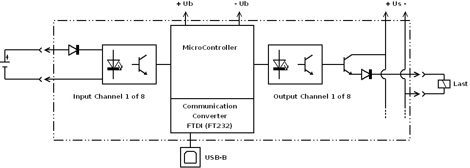 |
| XUP01R | 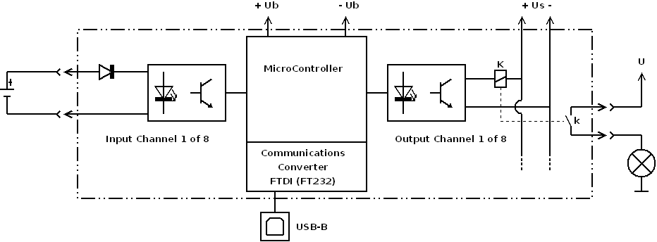 |
Driver Installation
The module registers itself on the PC as a Virtual COM Port (VCP). For operation, the corresponding driver from FTDI is necessary. Under modern Windows versions (10/11), this is usually installed automatically via Windows Update.
If this does not happen, the drivers can be downloaded manually:
- Driver Download: FTDI Chip VCP Drivers
After installation, the module appears in the Windows Device Manager under "Ports (COM & LPT)" as a new USB Serial Port (e.g., COM3). This COM port number must be selected in the software (MFR-Setup or custom application).
Available Modules
| Module | Image | Shop Link |
|---|---|---|
| XUP01L | 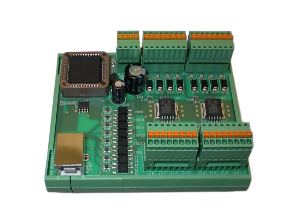 | Webshop |
| XUP01R | 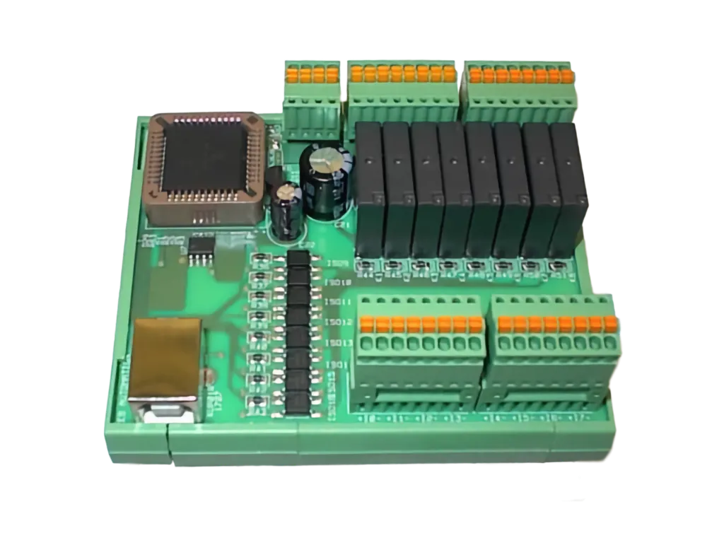 | Webshop |